
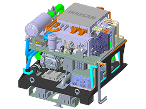


Load-Following Fuel Cell
PEMFC for Natural Gas
It is a fuel cell with On-Off control capability and high load-following ability that can flexibly respond to power demand.
-

Load-Following Fuel Cell
PEMFC for natural gas has the advantage of On-Off control and the ability to adjust the power generation according to power demand. It is a fuel cell optimized for load-following operation, flexibly responding to the variability, intermittency, and oversupply of other renewable energies.
-

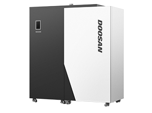
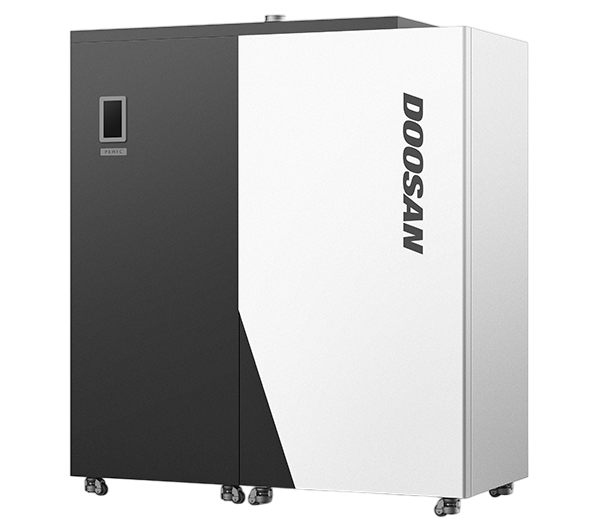
Small Installation Area
With a system area of 0.35㎡ (based on PEMFC for natural gas 1kW), it is designed for easy installation in confined buildings in urban areas. It can be installed in a limited basement area, eliminating the issues and costs associated with securing a site.
-

Distributed Energy that Can Be Installed Near the Demand Site
With high electrical efficiency, simultaneous production of heat and electricity, and a small installation area, it can be installed near high energy consumption areas such as urban areas and industrial complexes, allowing it to function as distributed energy.
-

Fire and Explosion Safety Secured with Explosion-Proof Design
Fire and explosion safety is enhanced with explosion-proof design, and the application of dual flame detection sensors shuts off the gas within seconds in the event of an LNG leak.
PEMFC vs SOFC
| Capacity | PEMFC | SOFC | Key Features and Advantages by Fuel Cell Type | |
|---|---|---|---|---|
| Electrolyte | Polymer Electrolyte | Solid Oxide |
[PEMFC] · Load-following operation enables easy adjustment of power generation according to electricity demand. · High thermal efficiency is advantageous when there is high demand for heat utilization such as hot water. [SOFC] · High electrical efficiency is advantageous for sites with high electricity usage or those requiring continuous power generation. |
|
| Operating Temperature | 60 ~ 80℃ | 600 ~ 1,000℃ | ||
| Efficiency | Electricity | 35 ~ 40% | More than 50% | |
| Heat | More than 50% | 30 ~ 45% | ||
| Operating Characteristics | Capable of constant On/Off operation 24-hour continuous operation possible |
24-hour continuous operation possible | ||
PEMFC for Natural Gas Specs
 |
 |
|
 |
|
To be released |
|||
| Capacity | kW | 1 | 6 | 6 | 10 | 10 | 50~150 | |
| Efficiency (Electric/Overall) |
KS | % | 36.4 / 83.7 | 40.1 / 97.8 | 39.2 / 97.0 | 37.6 / 94.6 | 37.7 / 94.7 | |
| KGS | 35 / 94 | 39.31 / 93.86 | 38.94 / 93.32 | 38.41 / 96.76 | 38.14 / 96.12 | |||
| Fuel | NG | NG | NG | NG | NG | |||
| Fuel Consumption | Nm3/h∙kW | 0.26 | 0.26 | 0.26 | 0.26 | 0.26 | ||
| System size (W x D x H) |
mm | 650 x 550 x 1,580 | 1,700 x 740 x 1,800 | 1,700 x 740 x 1,800 | 1,700 x 740 x 1,800 | 1,700 x 740 x 1,800 | ||
| Weight | kg | 270 | 780 | 780 | 800 | 800 | ||
| Supply and Exhaust Type | FF | FF | FE | FF | FE | |||
| Power Supply | AC 220V / 60Hz (Single Phase) |
AC 380V / 60Hz (Three-Phase Four-Wire System) |
AC 380V / 60Hz (Three-Phase Four-Wire System) |
AC 380V / 60Hz (Three-Phase Four-Wire System) |
AC 380V / 60Hz (Three-Phase Four-Wire System) |
|||
| Start-Up Time | min | < 88 | < 106 | < 105 | < 104 | < 99 | ||